Custom Vuforia VuMarks to identify and monitor IoT Devices with HoloLens
Some of the most popular experiences of Augmented or Mixed Reality are currently in a gaming or an immersive 3D form. But what makes headsets like the HoloLens so different and special is the ability to still see into the physical world. It is this link that opens up so many new opportunities and future possibilities of spatial computing. An interesting scenario is using HoloLens to interact with IoT devices in the real world. Just by gazing at devices around a room imagine you could identify a specific IoT device to review its real-time telemetry and control it over the air!
Setting up some sample IoT devices to interact with…
To test out this scenario the first thing we need here is access to some IoT devices to identify. In our case and for sake of simplicity we use some simulated IoT devices using the Azure IoT Solution Accelerators Remote Monitoring sample which you can try out.


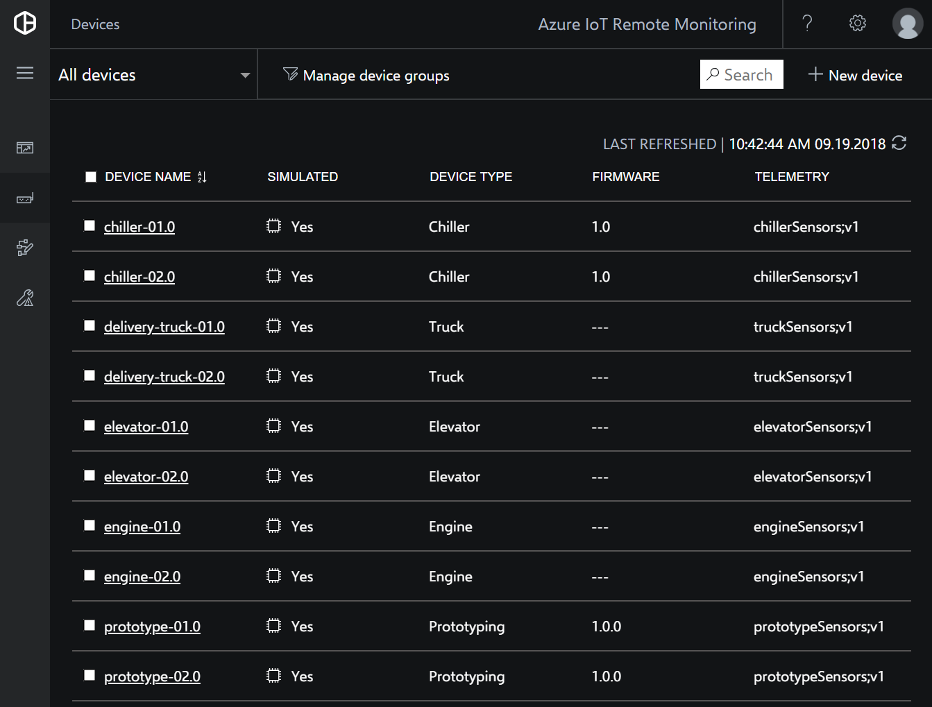
Once the Azure IoT Remote Monitoring solution is provisioned and ready you can select it to review a list of devices. This provides us with the list of Device Name Ids we will use to generate the VuForia VuMarks in the next steps.
Identifying IoT devices in the real-world using VuForia VuMarks
The second thing we need is to be able to identify each IoT device in HoloLens. One approach we tried during a HoloLens hack was to use Vuforia VuMarks to identify each device. A VuMark template contains a particular type of encoded data; numeric, string or raw bytes. Initially I tried out the default numeric type VuMarks from the VuForia Samples to check everything was working before trying anything more complex. Bear in mind there will also be a number of physical and environmental factors including VuMark placement, size and lighting conditions in the area to test and consider.
Tip: I found it useful to test the VuMarks by saving all the generated images on my iPhone and testing them in the Unity Editor using the built-in web cam.
Creating a custom VuMark
I used the VuForia VuMark Illustrator template to create a custom VuMark. In my case I wanted to a support a 32 character length string to contain a GUID so I created a string type VuMark with 280 data elements. To save time designing your own VuMark you can download my finished custom GUID VuMark SVG. If you want to create your own VuMark I’ve included a list of VuMark element requirements below so you can get an idea of how complex the design would need to be and compare how many elements are required for each data type:
| Id length | String elements required | Byte elements required |
|---|---|---|
| 1 | 35 | 40 |
| 4 | 56 | 64 |
| 8 | 84 | 96 |
| 10 | 98 | 112 |
| 11 | 112 | 120 |
| 12 | 119 | 128 |
| 14 | 133 | 144 |
| 16 | 147 | 160 |
| 18 | 161 | 176 |
| 20 | 182 | 208 |
| 22 | 196 | 224 |
| 24 | 210 | 240 |
| 32 | 280 | 320 |
| 48 | 406 | 464 |
| 64 | 546 | 624 |
| 100 | 840 | 928 |
| Maximum numeric Id | Numeric elements required |
|---|---|
| 9 | 28 |
| 99 | 31 |
| 999 | 34 |
| 9999 | 38 |
| 9 x5 | 41 |
| 9 x6 | 50 |
| 9 x7 | 54 |
| 9 x8 | 57 |
| 9 x9 | 60 |
| 9 x10 | 64 |
| 9 x11 | 67 |
| 9 x12 | 70 |
| 9 x13 | 74 |
| 9 x14 | 77 |
| 9 x15 | 80 |
| 9 x16 | 84 |
| 9 x17 | 87 |
| 9 x18 | 90 |
| 9 x19 | 94 |
For more info on designing VuMarks you can download the VuMark design guide or view design guide docs. I also found the video explaining the VuMark design process to be most helpful. NB: To design your own custom VuMarks you will need Adobe Illustrator to run the VuMark template scripts.
Illustrator / VuMark Scripts troubleshooting notes:
- You may have to restart Illustrator after copying the scripts into the
C:\Program Files\Adobe\Adobe Illustrator CC 2018\Presets\en_US\Scriptsdirectory. - If you hit an error when setting up a new VuMark using the Illustrator scripts v6.0.112 then check you have Adobe’s Myriad Pro fonts installed.
- If you can’t see the Illustrator canvas or the document area is blank or black then you might have to disable GPU acceleration under Preferences > Performance.
Creating custom VuMark database for Unity
Once you’ve designed your custom VuMark in Illustrator and it passes all the tests you will be ready to export your VuMark Template artwork. If you don’t have your own design ready you can download my GUID VuMark SVG artwork.
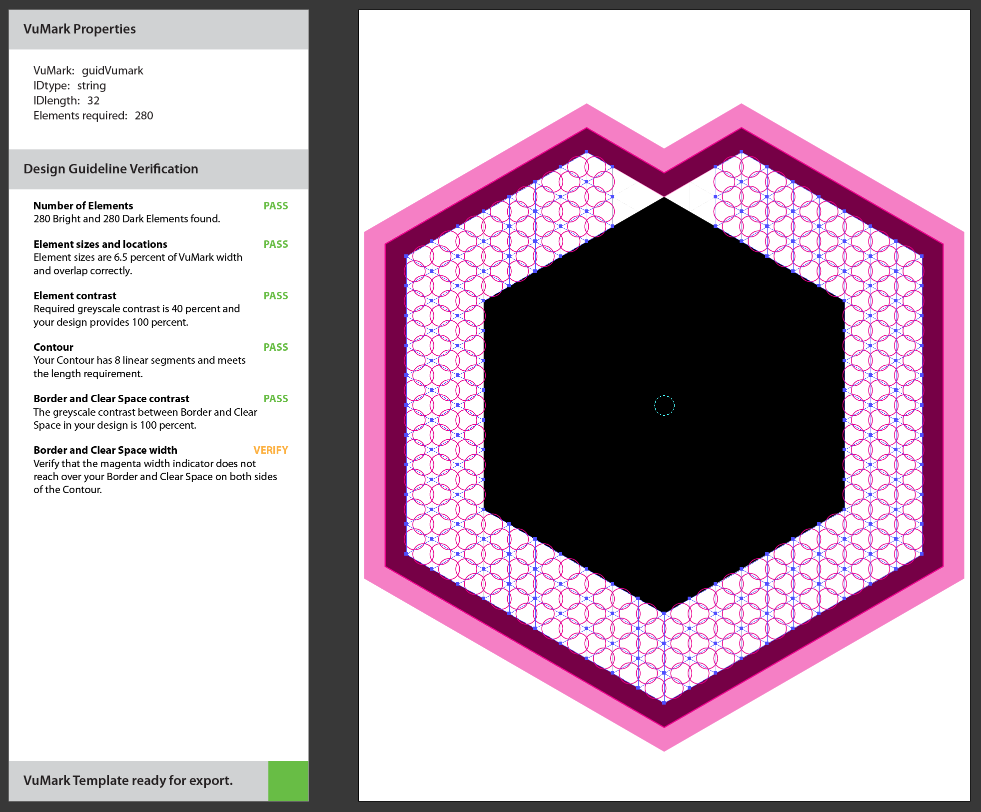
Note: If you’re starting a new design it’s preferable to avoid rotational symmetry in your VuMark’s border or contour otherwise you will have some additional work to do, as well as this the validation scripts don’t seem to provide a clear indication if this is completed correctly. You might also notice the Border and Clear Space width is only shown as “VERIFY” status - this check is left to the designer to manually check that the magenta overlay around the VuMark contour falls within the border and clear space boundary.
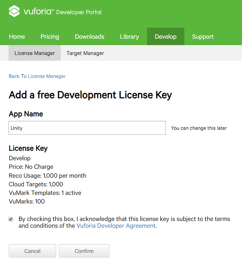
- If you haven’t used VuForia before you will have to create a developer account and get a free license key for development in Unity.
- Create a new VuMarks database.
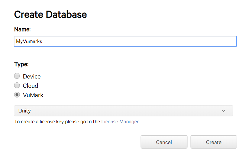
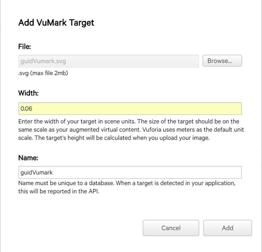
- Upload the custom VuMark SVG artwork file into your VuMark database. Note: You should set the width of the VuMark in relation to Unity’s unit of measurement which is in meters. In my case I want to recognize the VuMark on my iPhone which is 6 cm wide therefore I use a value of “ 0.06” m.
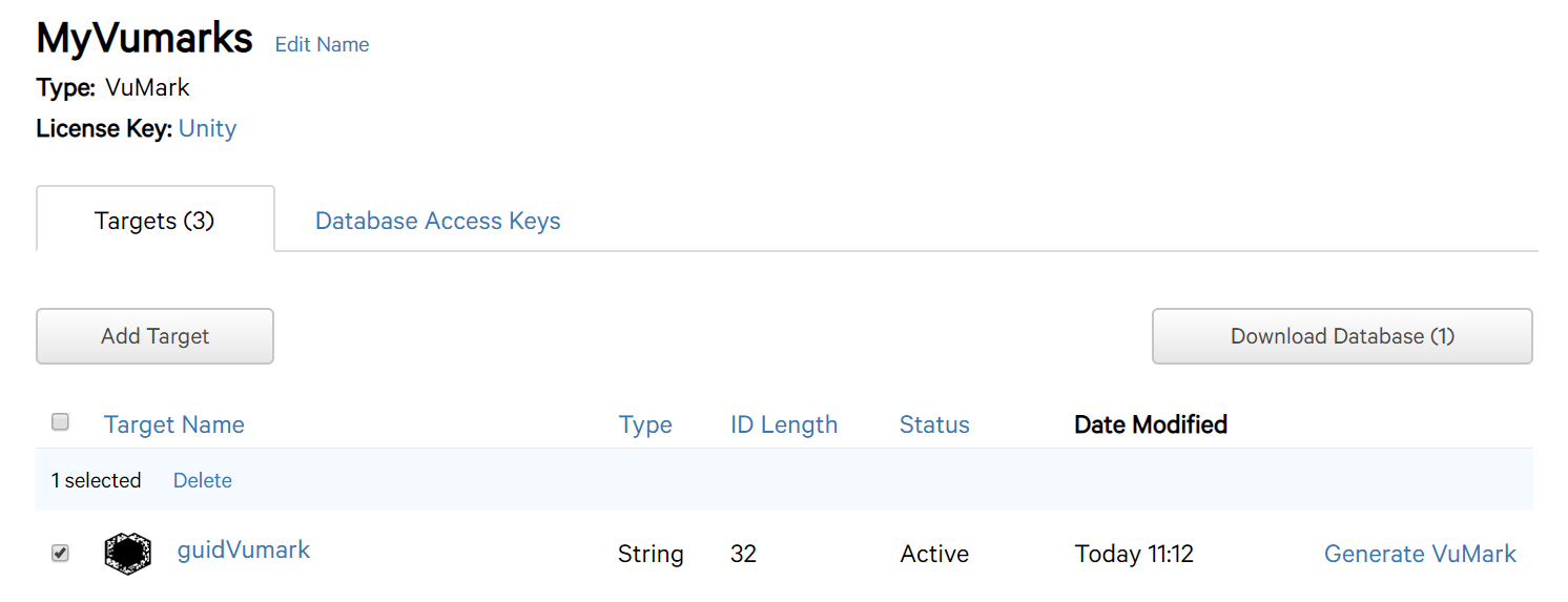
- Select your VuMark template target to download as your VuMark database.
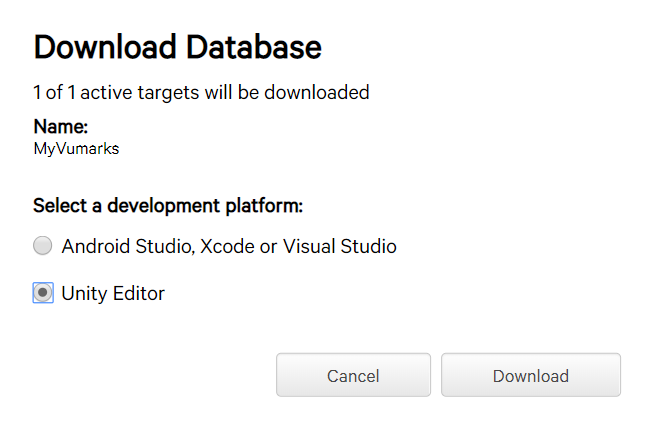
- Download database for Unity Editor.
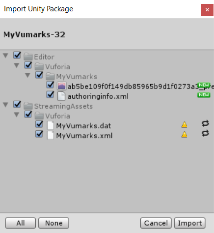
- Import your VuMarks database package into Unity project. If you don’t have your own Unity project you can setup the Mixed Reality IoT Monitoring sample to get started.
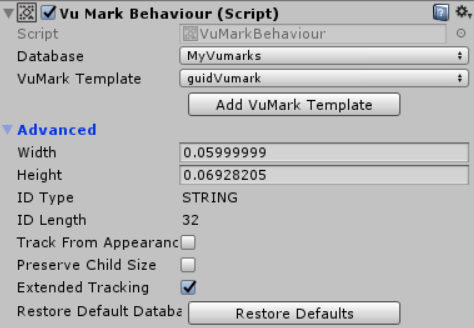
- In Unity scene check the VuMark Behavior is setup correctly with your custom VuMark Database and Template and has Extended Tracking enabled for Mixed Reality.
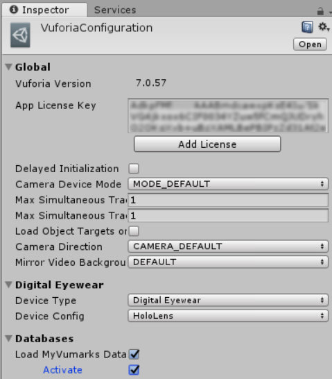
- Open the VuForia AR Camera configuration settings to enter your VuForia developer license key and to load and activate the VuMark database.
- Generate the VuMark images for each Device Id you want to recognize.
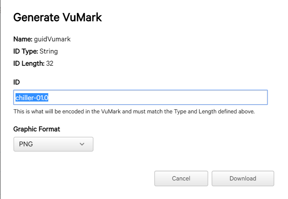
For my sample IoT devices I generated the following device Ids; “chiller-01.0”, “chiller-02.0”, “elevator-01.0”, “elevator-02.0”, “furnace-01.0”.
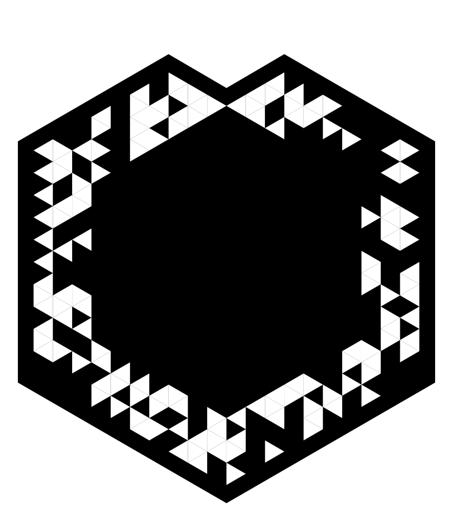
Tip: Save the generated VuMark images to iPhone / Android to test with. (I just saved the generated VuMark PNG images to my OneDrive images folder to sync onto my iPhone.)
Running the sample Mixed Reality IoT Monitoring Unity project
To run the Mixed Reality IoT Monitoring Unity project you will also need to setup the Azure Function APIs to get the device data from the Azure IoT Remote Monitoring sample.
Azure IoT Device Functions (Nodejs backend)
- Fork the Azure IoT Device Functions project on github.
- Sign in to your Azure portal
- Create a new Azure Function. NB: Ensure your Function app settings is using version 2
-
Add the following environment variables using your Azure Function app settings :
- IOTHUB_CONNECTION_STRING
- TSI_FQDN
- AD_APP_ID
- AD_APP_KEY
- AD_TENANT_DOMAIN NAME “*.onmicrosoft.com”
- To deploy your Function app select Platform Features > Deployment Options > Setup > GitHub and choose your forked repo.
Next steps…
Using VuForia VuMarks we are able to identify an IoT device using a HoloLens. Then using the recognized device Id as a param we can poll an Azure Functions endpoint to return the device’s telemetry. The next steps in this scenario would be to add buttons to call methods listed in the device’s payload.